- Phone:+86-17331948172 +86-0319-8862898
- E-mail: inquiry@puxingclamp.com
iun. . 27, 2025 09:30 Înapoi la listă
Pipe Clamp Load Capacity
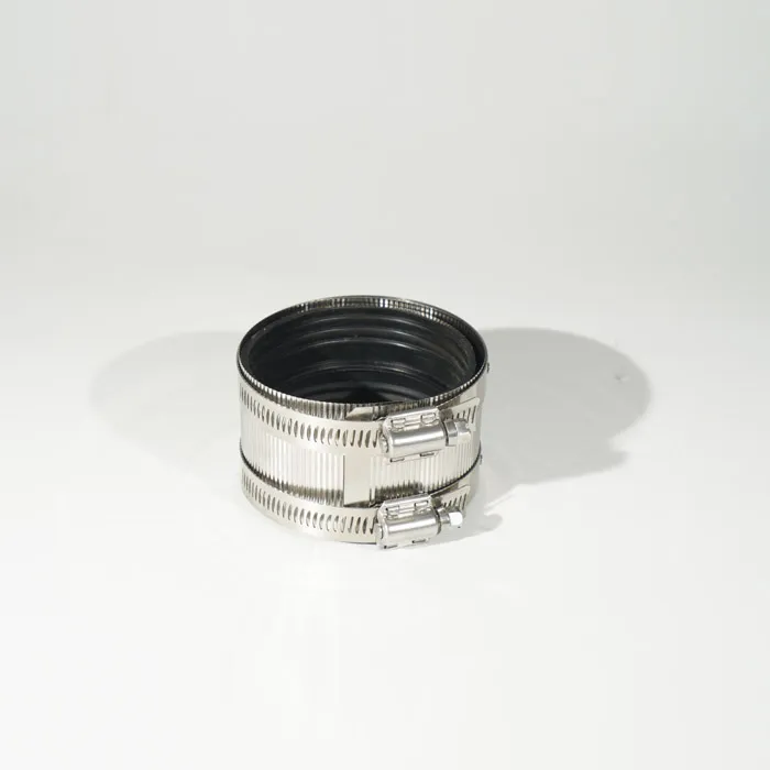
Pipe clamp load capacity represents one of the most critical factors in designing safe and reliable piping systems across industries. Whether using standard tube clamp designs or specialized stainless steel hose clamp configurations, understanding the mechanical limits of these essential components prevents system failures, leaks, and potential safety hazards. The load capacity of a clamp determines how effectively it can withstand various forces including internal pressure, vibration, thermal expansion, and external mechanical stresses.
This comprehensive guide explores the engineering principles behind pipe clamp load ratings, factors affecting performance, and best practices for selection and installation. From oil and gas pipelines to HVAC systems and marine applications, proper understanding of pipe clamp capabilities ensures long-term system integrity and operational safety.

Understanding Pipe Clamp Load Capacity Specifications
The load capacity of pipe clamp systems depends on multiple interrelated factors that engineers must consider during system design and component selection. Unlike simple fasteners, these clamps must accommodate dynamic loads and varying environmental conditions throughout their service life.
Key Load Capacity Metrics
Radial Load Capacity: Resistance to bursting forces from internal pressure
Axial Load Capacity: Resistance to sliding along pipe length (often 200-5000 N depending on clamp type)
Vibration Resistance: Ability to maintain grip under cyclic loads (tested to 10 million cycles for premium tube clamp)
Temperature Effects: Load capacity variation across operating range (-40°C to 400°C for stainless steel)
Material Considerations
304/316 stainless steel offers 30-50% higher load capacity than galvanized
Cold-rolled strip provides 15-20% greater strength than hot-rolled
Hardness range HRB 70-90 optimizes strength without brittleness
Material thickness (typically 0.8-2.0mm) directly impacts capacity
Design Factors
Band width correlates with load distribution
Number/size of tightening bolts affects clamping force
Surface finish influences friction coefficients
Bending radius impacts stress distribution
Lining materials modify grip characteristics
These specifications demonstrate why our stainless steel hose clamp products undergo comprehensive testing - including burst pressure, cyclic fatigue, and salt spray evaluations - to verify performance under real-world conditions that exceed typical operational demands.
Comparing Load Capacities Across Pipe Clamp Types
Not all pipe restraint systems offer equivalent load-bearing capabilities. Understanding the differences between standard pipe clamp designs, specialized tube clamp configurations, and high-performance stainless steel hose clamp products ensures proper selection for specific application requirements.
Standard Pipe Clamps
General purpose designs for light-medium duty
Typical axial capacity: 500-1500N
Radial pressure rating: 150-500 psi
Common in residential plumbing and HVAC
Economical but limited in harsh environments
Application-Specific Considerations
Oil/gas pipelines require 4X safety factors
HVAC systems need thermal cycling resistance
Marine applications demand saltwater immunity
Food processing requires crevice-free designs
Pharmaceutical needs ultra-clean surfaces
Our stainless steel hose clamp manufacturing process incorporates cold-rolled strip technology and precision forming to achieve consistent load capacities that meet ASTM, DIN, and ISO standards for even the most demanding industrial environments.
Engineering Principles Behind Pipe Clamp Capacity
The theoretical foundations of pipe clamp load capacity derive from mechanical engineering principles that govern material strength, friction dynamics, and force distribution. These principles guide the design of high-performance tube clamp and stainless steel hose clamp products.
Material Stress Analysis
Tensile strength calculations for band material
Shear stress on fastening components
Bending moments at clamp edges
Fatigue life predictions for cyclic loading
Creep resistance at elevated temperatures
Friction Mechanics
Static vs dynamic friction coefficients
Surface roughness effects on grip
Lining material selection (rubber, PTFE)
Preload optimization for vibration resistance
Torque-tension relationships
Force Distribution
Multi-point load sharing in band clamps
Stress concentration mitigation
Uniform pressure distribution
Moment arm considerations
Thermal expansion accommodation
These engineering principles inform our stainless steel hose clamp development process, where finite element analysis and physical prototyping validate designs before production to ensure reliable performance under specified load conditions.
Installation Factors Affecting Realized Load Capacity
Even the highest-rated pipe clamp can underperform if installed incorrectly. Proper installation techniques maximize the load capacity of both standard tube clamp products and specialized stainless steel hose clamp configurations.
Surface Preparation
Pipe surface cleanliness (remove oils, debris)
Proper alignment before tightening
Verification of roundness (out-of-round limits)
Lining material inspection (if applicable)
Identification of proper clamping location
Spacing Guidelines
Follow engineering spacing charts
Account for weight concentrations
Consider thermal movement requirements
Include vibration dampening needs
Allow for inspection access
Quality Verification
Post-installation visual inspection
Movement testing (push-pull verification)
Ultrasonic bolt tension measurement
Periodic re-torquing schedules
Load testing samples from production
Proper installation of our stainless steel hose clamp products ensures they achieve their rated load capacities while preventing common failure modes like slippage, fatigue cracking, or stress corrosion.
FAQs About Pipe Clamp Load Capacity
How does temperature affect pipe clamp load capacity?
Elevated temperatures reduce the load capacity of most pipe clamp designs due to material softening and thermal expansion differences. Our stainless steel hose clamp products maintain higher percentages of room-temperature capacity at elevated temperatures (up to 400°C) compared to standard carbon steel clamps.
Can multiple clamps share a load on long pipe clamp runs?
Yes, properly spaced tube clamp installations distribute loads across multiple points. Engineering calculations must account for the number of clamps, spacing intervals, and total system weight to ensure no single clamp exceeds its rated capacity during operation.
What safety factors are used in pipe clamp ratings?
Industrial stainless steel hose clamp products typically incorporate 4:1 safety factors - the actual failure load is four times higher than the rated working capacity. This accounts for installation variables, material degradation over time, and unexpected load cases.
How often should pipe clamps be inspected for load capacity maintenance?
Critical systems using high-performance pipe clamp components should undergo visual inspections quarterly and thorough torque/load testing annually. Harsh environments may require more frequent checks to ensure maintained capacity.
Do lined pipe clamps have different load capacities than unlined versions?
Yes, lined tube clamp designs typically have 10-20% lower axial load capacities due to the compressibility of the lining material, but often provide better vibration resistance and pipe protection. The specific reduction depends on lining thickness and material properties.
As piping systems face increasing demands from higher pressures, more aggressive media, and extended service life requirements, the importance of verified load capacity data becomes ever more critical. Our ongoing research and development in stainless steel hose clamp technology continues to push the boundaries of what's possible in pipe restraint systems while maintaining the safety margins that industrial applications demand.
-
The Impact of Automation on Crimp Hose Clamp Kit Production
ȘtiriAug.08,2025
-
Quality Control Measures in Precision Stainless Steel Strip Production
ȘtiriAug.08,2025
-
Market Analysis of China's Mini Hose Clamp Industry
ȘtiriAug.08,2025
-
How Stainless Steel Strip Enhances the Durability of Hose Clamps
ȘtiriAug.08,2025
-
Customization Options for American Type Radiator Hose Clamp
ȘtiriAug.08,2025
-
Compatibility and Installation Best Practices for Stainless Steel Hose Clips
ȘtiriAug.08,2025


